Indie game storeFree gamesFun gamesHorror games
Game developmentAssetsComics
SalesBundles
Jobs
Tags

valhallaCNC

58
Posts
20
Topics
A member registered Dec 24, 2021

Recent community posts

Hi Charlie,

I was going to update my tool library. I have old tools I want to remove, also want to rename some existing ones. I need to add new ones. I know how to do all of this. My concern is all the projects I have done. I believe each project stores the tools needed for that job. How does the project recognize the right tool, is it by name, tool number, or some other way?   By renaming or reordering does the project tools get messed up ?  Hope that's clear enough...

Thank Joe

Hi Charlie..

I got that part, sorry my question wasn't clear enough. I was talking  about the actual g-code file itself. At the top of my g-code I manually put comments about canvas size(x-y-z), point of origin and the tools I need for that project. I was asking about editing the UCCNC Post Processor File to be able to include that information automatically . I don't see any options about that. Hope that's better explanation, questions seem so clear before coffee...

Thanks Joe...

Hi Charlie...

I do different size projects, my projects are mostly one off signs. My canvas is always a different size and my origin point changes. Is there a ways to add canvas size (x-y-z),also point of origin in the header, and tools needed for entire project automatically ?  I add all these thing manually now.

Thanks Joe

Thanks Charlie...totally missed that in the users guide.

Joe

(1 edit)

Hi Charlie..

I did a project that was narrow along the X axis , but very long along Y axis. When I generated a tool path with parallel carving, the tool path would be X axis  direction only . Is there a way to make it cut in the Y axis direction ? I looked at your tutorials and options for the cut but did not see how to do this. When it generates the tool path does it look at which is more efficient ? 

Thanks Joe

(1 edit)

Hi Charlie...Long time

Been busy building  new shop, question of the day for you. I finished a project , and was fine tuning it. I was trying to compare before and after changes. The only thing I could come up with is starting 2 pixelcnc side by side. Is there a way to do this on one canvas ? Something like a view only mode for the imported item. I did try to take a screen shot and open that, but that didn't work for me.

Thanks Joe...

Looks great...I know nothing about Lithophanes, How deep are the cuts to get that effect ?

(1 edit)

Hi Charlie..

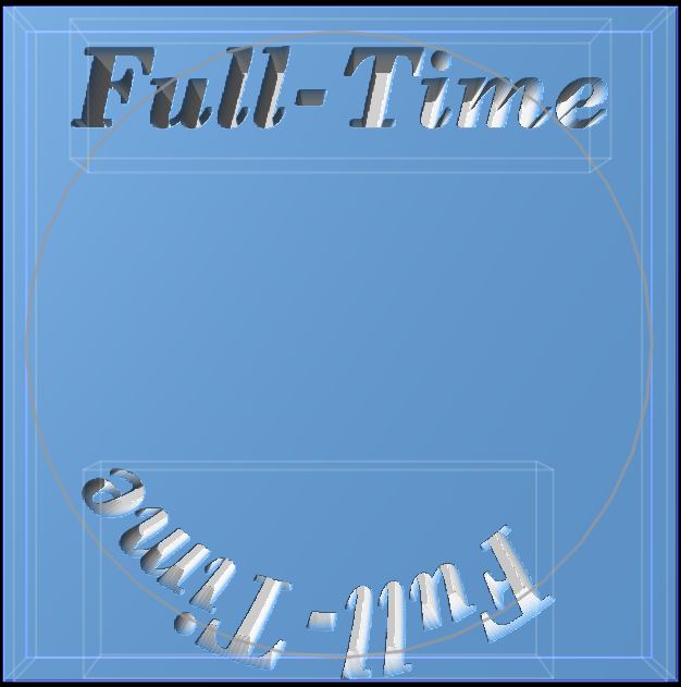
Working with text on a circular path. I generate my layer with text on a path , works fine . I use position offset to get it to the top of the circle. However when you get too many letter position offset max's out at 1 , cant center it to circle path top, when text is centered on the circle it seems. I have to generate the raster layer, and use rotation of the raster layer to complete positioning. Is there a reason it max's out at 1 ?  Not an issue just a question.

Joe....

This is not a program issue, just trying to understand better...After I create the image layer. Then I rotate it -90 , then stretch it to 47 along the Y axis of the canvas . but the image is stretched on the X axis to 47.  I was expecting to see the X - Y size switch on the image after I rotated it 90. Clear as mud...I make things harder then they are sometimes..

Joe...

Laying out large sign. Canvas X=24" , Y =48" .  When you create a image layer or text layer , It is always created on the X axis. I can rotate it 90 degrees and size to fit canvas but it keeps the original import orientation. the created layers have X=46 , Y=22 after resizing . Is this correct ?  , doesn't make a difference in the final product.

I found a nice third party utility. Looks like it will do the trick very easily. Only does two parts , but that is enough for me this time.

Joe..

(1 edit)

Hi Charlie...

I have the opportunity to do a large sign. I know there is not a tiling function in PixelCNC. I'm not even sure you call it a function.  Is there a work around for that ? I am going to try square layers abutted with the words and design on top of that, with some registration holes to line everything up. Or am I way off base here ?

Thanks Joe.....

(1 edit)

That works great ...Makes work flow much easier....very nice how it updates the project tool list when you change tools in the operation tab.

thanks Joe......

Thanks Charlie...

When I got the pop-up I assumed you still had to load the list. That clarifies things

Joe....

How do you delete a tool from the Tool Library...I can delete it from the tool project list, but I haven't even been using the loaded tool project list. It's much easier to just pick you tool from the operation tab. I get to see my whole list of tools that way. Just an observation , the project tool list is populated from the first ten in the library correct ? You have to load tools before you can start an operation.   Would it be better to populate the project tool list from the operation tab selection . That way only the actual tool you used would be in the project list. 

Thanks Joe

Thanks for the work-around Charlie. I would never even think of that combination. 

Joe...

Thanks Charlie...I missed that part on the tutorial. Got it working now except for one thing. when the text is on the bottom , I can't get it to read right to left with the correct orientation. I've tried flipping the original several different combinations. But can't seem to get this, probably staring me in the face.

(1 edit)

Hi Charlie..

Is there a way to do a round canvas , other then drawing a circle layer ? I have some round projects , and want to see how everything fits on the round. Whats the best way to put text on a curve ?

Thanks Joe

Sounds good Charlie..I know the value of feedback...this forum  feels like my personal tutor is all. But it is great customer service....

Charlie..

I think we are talking the same thing. I misspoke , I understand the project tool list is  separate from tool library. I didn't know about the 10 operation limit, seems like that is plenty. I wasn't very clear. I was just thinking to display all your tools (even if there is more then 10) , being able to sort them directly without having to call up the second sorting box, then have the ones you use in operations added to the project tool list automatically such as you described .  Sounds like the same thing we are talking about. Have you had feed back from anyone else, hope your not making changes on my account.

Joe

(4 edits)

Charlie..

I understand the library list is for separate projects, to add tools as needed for the currant project. I tend to load the whole 10 slot library list (less clicks).  I have more then 10 tools. When you use the sorting tool options, it does not affect the original 10 slot list, only selected tool from the original list. The second tool menu (load tool sorting one) works great, can that be displayed all the time instead of just the 10 slot list, or does that defeat what you had in mind ?  Or scroll bar on library list ? It would save steps going back and forth, to get to tools not on my original 10.  Just load the whole list on startup. When you save the project saves only the tools that are used, on reopening displays only those. I'm not always sure on which tool I want to use and sometimes like to try several before I settle on one. Or  maybe I just need to adjust how I use it. Curious how other people use this as well. Do you have any feedback ? This is not intended as criticism, but based strictly on the way I use PixelCNC. Hope you can understand my explanation.

Joe...

Charlie.. 

I made a bunch of templates, with all  the different styles I use.  I either work off them or use them for reference what worked the best for me. With the templates my tools load and my feed, speed and other parameters are set. I may just have to tweak them, but don't have to reinvent the wheel every time. Works OK for me that way.

Joe..

Charlie..I started from scratch like you suggested, it worked that way. The end result was the same as my setup.  I went back through my projects I have cut and they were all with canvas Z-fill set at 0.  I assume your setup ( Z-fill to top) is the preferred way . Is there a rule of thumb for canvas layer Z-fill setting, depending on the type of project ?

BTW ..update looks great,have not went through all the new options yet. I did  try the new medial path cut, that works great .

Thanks Joe

(1 edit)

Charlie..

It did not work the way you suggested.  However I set it up with canvas Z-fill to 0. Then I set each text layer with Z fill to top in this case .75 , inverted was checked and I used blend mode set to Difference. That let all layers be visible at the same time. I was able to set the cut on one operation. This was an add-on font, it looks like some fonts want a different setup, I used 2 different fonts one I had to invert and Z-fill differently to get it to work. I keep forgetting about the blend mode, I'm not 100% sure on its effects I'll have to work on that . You got me pointed in the right direction.

Thanks Joe...

HI Charlie..

New week , new question.

This is my first sign where I have multiple line of text. This will be a medial carve . I can create the 3 layers of text fine and  the font looks great. When I setup for project operation only one text layer can be visible at a time, or none will show. I have to do a separate operation for each text layer, even thou they are the same carve type.  I can't merge the layers, that option is  greyed out. Am I missing something ? 

Related question , what is the best way to get vertical spacing the same on multiple lines, is there a shortcut other then math ?  I think you had said you were working on alignment tools. Just looking for a shortcut in the meantime.

Thanks Joe...


(1 edit)

I got all that...it sets up perfectly with words or other objects. It only seems to happen on the one  SVG file. I haven't figured out whats different about it yet. GOT IT... I have to load vector as a paths- layer then generate a shape from it . Then it carves  correctly. Must be something peculiar about that SVG file .

HI Charlie...

Update looks good, upgrade went smooth. Glad it didn't change my UI custom colors .

I was trying to do a simple V-carve using a SVG load image/vector as raster layer. When I set the medial axis carving in the operation , I have set my cut depth and max depth to .2 , Contour Z to 50% , Depth offset to 0. When I generate the cut it barely carves the surface. If I use profile operation it will cut to the correct depth. The only way it will get to depth on medial carve is if I change Depth offset to  a positive number in this case .2   This is the first SVG I tried using. Any  thought on what I'm doing wrong ? Thanks in advance Joe....

(1 edit)

What you can't figure out my clear as mud explanation.....I figured it out,  all my layers were not on the same  X-Y zero. I must have moved one. Shifted my project off center.   It seemed like part of the canvas was included , It was user error. Thanks joe

Hi Charlie:

Most of my projects are cut-outs after carving. My project are X-Y zero centered. When I export it includes the canvas that could be bigger then the project. If my project is off centered from the canvas my X-Y zero is centered my project, but takes into account the whole canvas as exported size, not just cut layer. I have been using size canvas to layer , to get around this. Example if my canvas is 24 x 24 and my project is 8 x 8 it exports the 24 x 24 as overall size. Is fitting canvas to layer the best way to avoid this ?  

Thanks Joe

(1 edit)

That was the problem, got it working now. In your explanation you said It's a good idea to only make your canvas Z size as thick as you want your deepest cuts to be. Most things I do require a cut out, so I set my canvas Z size to my material depth (.75 ) .  Is that the best way to set canvas Z ?  I use profile operation to cut it out, and max depth will only go to Z size  ?

Charlie : It also will stall with the mountain layer even thou it is less then 1/2 of the letters. This is with any depth setting, not even touching the bottom layer.  So I just set Text layer as the active profile cut, works fine then. Is there any way to stop the calculation once it begins ? Otherwise I have to close and reopen  program. Thanks

(2 edits)

Opps...your right you were fixing pocket milling calculations on 12-9-21 emails. When I try to do profile operations same thing happens endless calculations. I can send log files if you need them...Joe ...BTW your second suggestion seems to work fine I'll know better after I cut it. Didn't know about the angle trick..thanks Update on my test. When the mountain and letters are on the profile operation it does endless calculations even with a very shallow cut (just letters). If I remove mountain layer it calculates correctly.

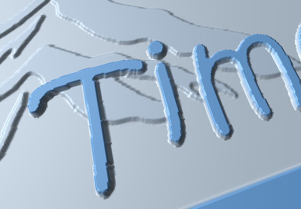
Hi charlie :  I'm stumped , I have two layers a raster layer of mountain and a text layer. I do a parallel rough pass first 1/4 EM. My second operation is with a round nose  EM to clean up. I wanted to get a crisp outline on the letters like a  Vbit profile but can't find the right operation order. The mountain in the back ground has varying heights . Any suggestions to point me in the right direction ?  Is  the profile operation that will be fixed in the next release the answer ?
Thanks Joe

Hi Charlie :

No hurry answering this. I've used pixel for several project now, I mostly do signs. One thing I have noticed when I'm designing a new project I have several layers in my design space. When I go to the project operation page I have to make sure I have the correct layers  visible. I may have several operations for a project and have to keep going back to the project canvas page  to enable or disable layers. When I make any changes I have to go through the whole process usually several times. A suggestion for you to think about, if you had a list of viable layers in the each operation and  you could set a layer as active for that operation. That would be separate from the project design page, then you would not have to keep going back and forth. Hope you could understand my explanation. Maybe it is just my work flow and I need to adapt more.

Thanks Joe...

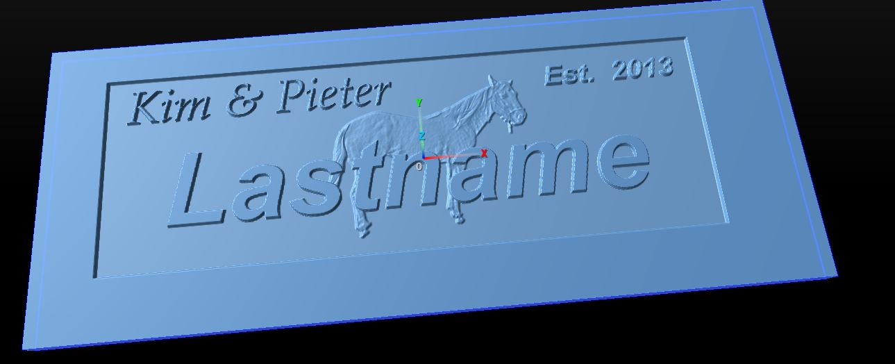
This was the final result. The horse came from a color cell phone jpg. I was surprised how well the color picture turned out, with tweaking of the levels.  The relief carving is about .075 max height .  The border is not that wide, I haven't did the cut out yet .

Thanks for the help Charlie.....

Hi Charlie,

I have been working with multiple layered carvings. I have been using a picture as a background using relief carve with parallel carving operation.  I know I can set the Z height of the layer, but that is not the true carved height. The only way I see to get the finished carved height of the picture is by watching the simulation of the Z axis data. I'm taking my work piece raster layer height( .75) ,  subtracting picture layer Z origin ( .6) that gives potential maximum height (.15).  I then take .15 and subtract Z height in the simulation for a given point , This gives me my carved height. Is this correct or am I missing a shortcut ?

Thanks Joe

Ok ..I got that. The canvas is just an overlay for your work-piece ?  You cant actually cut out the canvas ? You would need a raster path on the canvas , such as rectangle , oval or some other shape . Unless the work-piece does not need to be cut out and is already shaped as you want. then the canvas is just an overlay on that ?

Joe....

(1 edit)

Hi Charlie,

I have made several sign projects with various techniques. Raised letters, Vcarve, relief objects, etc.... All of my projects use a base raster layer. I don't understand where the canvas fits in. I know it defines your work space, but so does my base raster layer. The only thing as far as I see is if your project does not need to be cut out,then the canvas layer is the only thing needed.  Is the canvas layer redundant or am I missing the purpose and aimlessly wondering off ?

Thanks Joe

I'm never in a rush for answers...

My UI theme colors saves fine, I was wondering about back up for restoring if my PC crashes. So just backup my config file and I would be good to go.

Remembering the parameters would be all that's needed. It would save  alot of time trying to recreate after an edit on the base picture. I'll keep your todo list filled.......Thanks Joe

P.S. Pixelcnc has surpassed my expectations, even at this stage in its development. I have been using it exclusively for my projects. I'm still learning , there are alot of features.